

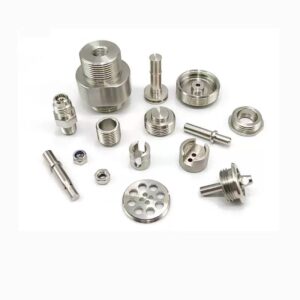
Turning Worm Gear Non-standard Reliable Worm and Worm Gear for Industrial Machinery
CNC Turning Worm Gear Non-standard Reliable Worm and Worm Gear for Industrial Machinery
- 説明
- レビュー (0)
説明
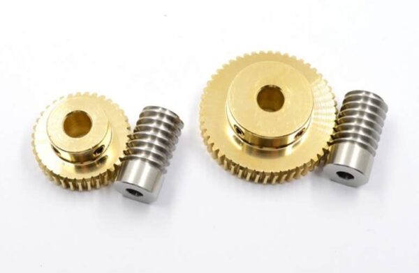
What is a Worm Gear?
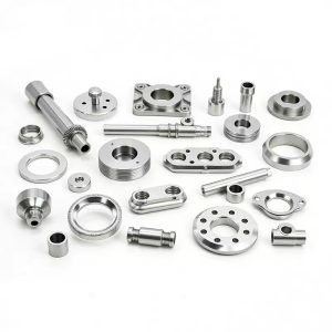
A worm gear system consists of two parts: a screw-like “worm” and a gear-like “worm wheel.” As the worm rotates, its threads push against the teeth of the wheel, causing it to turn. This design provides a high reduction ratio within a compact space. A key feature is its self-locking nature: the worm can drive the wheel, but the wheel cannot reverse-drive the worm. This prevents back-driving, making these gears ideal for applications that require holding a position, such as lifts and conveyor systems.
Materials
Worm: Typically made from hardened steel to resist wear, as it undergoes more revolutions and sliding friction. Common grades include carbon steel or alloy steel like 4140 or 8620, often through-hardened or case-hardened.
Worm Wheel: Softer than the worm to allow for a run-in period and better conformity. Common materials include:
Bronze: The most traditional and excellent choice for its wear resistance, low friction, and compatibility with steel. Cast bronze (e.g., SAE 65) is widely used.
Cast Iron: Used for low-speed, high-torque applications where cost is a primary concern.
Aluminum Alloy: For lightweight applications with moderate loads.
Plastics (e.g., Nylon, Polyacetal): Used for very light-duty applications, offering quiet operation and corrosion resistance.
Surface Treatments
Phosphating & Black Oxide: Provide a corrosion-resistant surface and help with initial run-in by retaining oil.
Hard Chrome Plating: Increases surface hardness and wear resistance of the worm.
Nickel or Zinc Plating: Primarily for corrosion protection.
Nitriding: A thermochemical process that hardens the surface of the worm for exceptional wear and fatigue resistance.
PTFE (Teflon) Coating: Can be applied to reduce friction and wear, especially during the initial run-in period.
Specifications
Reduction Ratio: Ranges from 5:1 to over 300:1 in a single stage. It is determined by the number of threads on the worm (starts) and the number of teeth on the wheel.
Module (Metric) or Diametral Pitch (Imperial): Defines the size of the gear teeth.
Center Distance: The distance between the centers of the worm and the worm wheel shaft, a critical dimension for housing design.
Pressure Angle: Common angles are 14.5°, 20°, or 25°, affecting strength and smoothness of operation.
Lead Angle: The angle of the worm’s thread, which influences efficiency and the potential for self-locking.
Direction of Rotation: Can be designed for right-hand or left-hand drive.
Application Fields of Worm Gear
Material Handling: Conveyor systems, elevators, and lifts.
Automotive: Steering systems (power steering gears), winches.
Machinery: Machine tools, packaging equipment, and indexing units.
Aerospace: Actuators for control surfaces and landing gear systems.
Consumer Products: Guitar tuning machines, fishing reels, and adjustable seats.
Excellent Case: A Heavy-Duty Industrial Conveyor System
In a large distribution warehouse, a heavy-duty conveyor system is used to move pallets up a significant incline. A worm gear reducer is chosen to drive the conveyor belt. The worm gear’s high reduction ratio provides the high starting torque needed to get a loaded pallet moving from a standstill. Most importantly, its self-locking characteristic acts as an inherent safety brake. If the motor were to lose power, the worm gear system immediately prevents the conveyor belt from reversing under the weight of the pallets, preventing a dangerous and damaging rollback. This ensures operational safety, protects the goods, and eliminates the need for an additional, external braking system, making the solution both highly effective and reliable.
レビュー
レビューはまだありません。